4.Function Settings
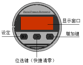
4.1 Key function description
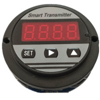
4.1.1 Set key "SET"
In measurement mode, press short to open and enter password settings.
When setting the mode menu to display, the short press is modified to enable the parameter, the current menu is displayed with the parameter value, and the short click on the confirmation parameter again returns the menu display state.
4.1.2 Shift key ""
Short press without function in measurement mode.
In the measurement mode, the zero function of the main variable is executed in 5 seconds.
Set the mode to shift and subtract one function.
4.1.3 Add the key ""
Short press and long press have no function in measurement mode.
In the setting mode, one function is added.
ADC collection menu short press for collection enabled.
4.1.4 Summary of key functions
The instrument realizes the setting and collection of all parameter input and calibration data through the three keys of the panel. The instrument setting and input take various optimization measures to improve the customer operating speed:
The shift key and the increase key of the instrument have variable rate function.
The instrument also has a shift and incremental input method. For menus that require a large number of changes, the shift method is used, and the menu that requires continuous input data is adopted incrementally.
The instrument will stop the analog output in the setting state. In the user setting mode, if the user does not have an operating instrument within 30 seconds, it will automatically exit to the measurement state.
The meter will save all set parameters only when it normally exits the menu.
4.2 Primary variable clearance
The primary variable clearing zero, PV clearing zero, is the zero point at relative atmospheric pressure, not the zero point of the sensor range. Place the transmitter directly under atmospheric pressure and press the "" key for more than 5 seconds to enter the primary variable zero function.
If the transmitter has performed a zero clearing operation, the zero clearing operation will be restored when the zero clearing operation is performed. If you want to re-zero the zero clearing operation, you need to perform another zero clearing operation.
The zero clearance range is 25 % of the variable delivery range, and zero clearance functions will not be performed if this range is exceeded.
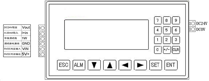
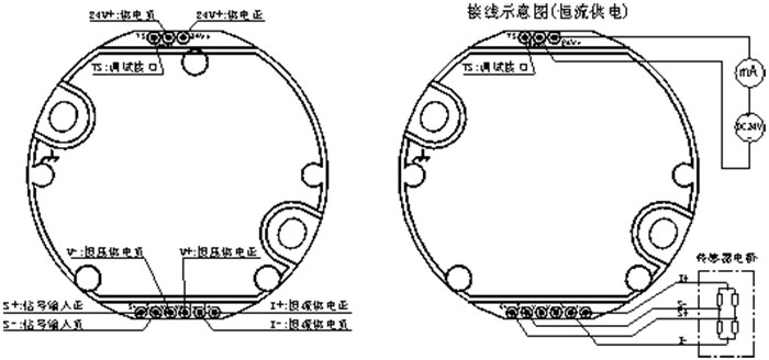
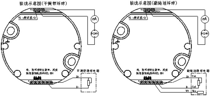
4.3Set Box Diagram

4.4 Menu description
This instrument menu is divided into "production debugging menu"; The "Ordinary User Menu" level is distinguished by the entry password of the menu at all levels.
"Production Debug Menu"
The entry password is "0066", which is used by the transmitter manufacturer. The basic parameters of the transmitter are set, and the accuracy, calibration value, and other parameters of the transmitter are determined. Therefore, the production debugging menu can not be opened to the general user to avoid calibration. The data is destroyed.
User menu
The entry password is "00016", which is used when performing some special settings for the transmitter on-site use requirements.
Note: When the user menu is set, if there is no key operation within 30 seconds, it will automatically exit the setting and return to measurement mode.
4.4.1 Password Settings Menu
Lock: Password Input Menu, Available(-1999 ~ 9999)
4.4.2 Factory commissioning menu
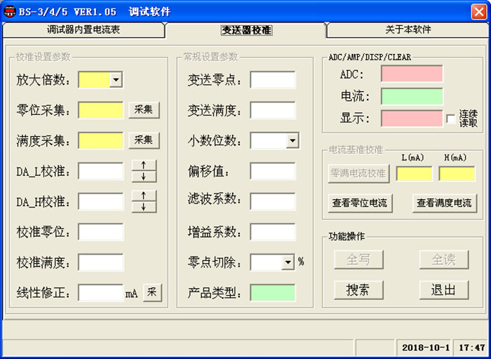
-Sn-: Input signal magnification setting, range can be set(1, 2, 4, 8, 16, 32, 64, 128, 256)
Because there are many types of sensors on the market, their sensitivity is inconsistent. The magnification can be adjusted by the panel button. The specific reference standard is that the sensor views the Ad-H menu value at full capacity. The absolute value of this value is generally reasonable between 10000 and 30000. Beyond this range you need to adjust the magnification. The general diffusion silicon is set to 16 and the ceramic is set to 128.
Ad-L: Zero bit collection
When setting this menu, you need to apply the pressure set by the "dP-L" menu to the transmitter. When you press the "SET" key, the collection value saved inside the header is displayed. When you press "" or "", start collecting this collection., After the data is stabilized, press the "SET" key again to confirm the collection.
Note: If the collection value is greater than 0x7000, you need to reduce the magnification in the "-Sn-" menu.
Set a limit margin for users to use to avoid overflow.
Ad-H: Full school
When setting this menu, you need to apply the pressure set by the "dP-H" menu to the transmitter. When you press the "SET" key, the collection value saved inside the header is displayed. When you press "" or "", start collecting this collection., After the data is stabilized, press the "SET" key again to confirm the collection.
Note: If the collection value is greater than 0x7000, you need to reduce the magnification in the "-Sn-" menu.
Set a limit margin for users to use to avoid overflow.
So-L: Zero current setting
This menu is the current output value at zero position of the transmitter range. It is necessary to concatenate a high-precision ammeter in the transmitter power supply loop, press the "" or "" key to modify the setting, and adjust the current to the standard 4mA or user. The required current value, Press the "SET" key to confirm.
So-H: Full Point Current Set, Available(3.900 mA to 21.000 mA)
This menu is the current output value at zero position of the transmitter range. It is necessary to concatenate a high-precision ammeter in the transmitter power supply loop, press the "" or "" key to modify the setting, and adjust the current to the standard 20mA or user. The required current value, Press the "SET" key to confirm.
-dP-: display precision setting, range(0 to 3)
The display resolution is the number of decimal places displayed during the measurement mode. The user can set it according to the requirements of the field use. The number of decimal places displayed is not as large as possible, and the stability of the display value should be guaranteed as a matter of priority.
DP-L: Standard quantitative range lower limit setting, can be set range(-1999 ~ 9999)
This setting corresponds to the zero bit pressure value added at the time of production.
DP-H: set the upper limit of the calibration range, with a range(-1999 ~ 9999)
This setting corresponds to the full point pressure value added at the time of production.
LINE: Middle Point Linear Correction Settings
To apply the mid-point pressure to the transmitter, see the actual current output of the transmitter. The theoretical current value of the mid-point of the transmitter minus the difference of the measured current value is a linear correction value, and note the distinction between positive and negative.
Note: In order to ensure the accuracy of the current output at the point in the transmitter, the linear correction value is calculated using the current value as a reference instead of the display when the mid-point correction of this table header is used.
ZErO: Zero full shielding coefficient, available range(0.00 to 1.00)
This menu setting represents a zero full screen range, and a zero full screen is turned off when setting the value "0.0". Example: Set to 0.10 indicates that when the transmitter output is close to 0.10 % of the zero or full point addition and subtraction range, the transmitter output will automatically stabilize at the zero or full point, and there will be no output pulsation due to interference. phenomenon.
BS-L: Variable range lower limit setting, range can be set(-1999 ~ 9999)
This feature can realize the zero passive migration of the variable output, and the set pressure value will correspond to the current value of the "So-L" zero current menu. In order to facilitate user settings, The minimum range of the transmitter can be compressed according to 3:1 of the sensor range, and the maximum range can be set according to 1:1 of the sensor range. Beyond this range will affect the output accuracy of the transmitter.
bS-H: Variable range upper limit setting, range can be set(-1999 ~ 9999)
This feature can realize the passive transfer of the full point of the variable output, and the set pressure value will correspond to the current value of the "So-H" full point current menu. The minimum range of the transmitter can be calculated according to the 3:1 of the sensor range. Compression, The maximum range can be set at 1:1 of the sensor range. Beyond this range will affect the output accuracy of the variable.
End: Exit Settings Menu
Under this menu, press the "SET" key, exit setting mode, and save setting data.
4.4.3 General user menu
BS-L: Variable range lower limit setting, range can be set(-1999 ~ 9999)
This feature can realize the zero passive migration of the variable output, and the set pressure value will correspond to the current value of the "So-L" zero current menu. In order to facilitate user settings, The minimum range of the transmitter can be compressed according to 3:1 of the sensor range, and the maximum range can be set according to 1:1 of the sensor range. Beyond this range will affect the output accuracy of the transmitter.
bS-H: Variable range upper limit setting, range can be set(-1999 ~ 9999)
This feature can realize the passive transfer of the full point of the variable output, and the set pressure value will correspond to the current value of the "So-H" full point current menu. The minimum range of the transmitter can be calculated according to the 3:1 of the sensor range. Compression, The maximum range can be set at 1:1 of the sensor range. Beyond this range will affect the output accuracy of the variable.
OFSt: Show offset values, range can be set(-19999 ~ 9999)
By setting this menu value, you can offset the transmitter display and output value. The default value of this menu is 0 from the factory. In general, there is no need to set this menu value.
Filt: Filter constant setting, set range(0 to 4)
The larger the filter constant value is set, the stronger the ability to suppress the interference, but the sensitivity will decrease. The default value of this menu value at the production time is "2" for medium filtering effect, which can adapt to most applications.
SPAn: Sensor sensitivity correction coefficient
During the use of the transmitter, if the sensor sensitivity changes, it can be corrected by this menu. If there is an error at the zero point of the transmitter before the sensitivity correction of the transmitter is made, The zero error of the transmitter should first be corrected by the primary variable zero clearance function to ensure that the sensitivity correction is linear and the variable is normal. This menu has a default value of "1.0000". This menu can also be used as a density correction for the liquid level transmitter. Convenient changes in the medium density of the customer is to adjust the transmitter output.
For example: The range of transmitter calibration is from 0.00000 to 20.00 MPa. After a period of time, the zero point becomes "0.05 MPa" and the full point becomes "20.16 MPa". At this time, the zero point and sensitivity of the transmitter have changed. When correcting it, the zero error of the main variable should be cleared by using the zero function of the main variable. After the zero variable is cleared, the zero point of the transmitter is "0.00MPa" and the full point is "20.11 MPa". Then calculate the theoretical full point divided by the actual full point value to correct its sensitivity, IE 20.00 MPa/20 .11 MPa = 0.994, the sensor sensitivity correction coefficient is modified to "0.994" to correct the sensitivity change.
End: Exit Settings Menu
Under this menu, press the "SET" key, exit setting mode, and save setting data.
|
